Putting this equipment on tracks ensures smooth linear motion with minimal maintenance required.
Reprinted with permission: The AWS Welding Journal
Downtime is costly for metalworking and fabrication shop operations of all sizes. Whether it’s multiple millions of dollars per hour of unplanned downtime at a Tier 1 automotive facility or $500 per hour of scheduled maintenance downtime for removing spatter and other debris in a small fab shop, welding shops lose money when downtime strikes. Another common cause of welding robot downtime is having to move the robot into different positions and reprogram it when welding long parts.
Adding a linear axis to articulated industrial welding robots can help. For example, using a linear axis enables welding robots to weld long parts by allowing you to bring the robot to the work area rather than moving the part. Moreover, this allows your welding automation to operate continuously, eliminating the downtime associated with repositioning.
Similarly, when it comes to extremely large parts, instead of moving the part around, you can use tracks to smoothly guide the robot to the weld area. Maybe your metalworking shop doesn’t have much floor space, and rather than deploying multiple robots at every welding station, you’d like to transport your welding robot from one station to another. On top of these benefits, adding a linear axis will help your facility optimize welding performance and throughput, reduce downtime, and gain a competitive advantage.
Two primary reasons for adding a seventh axis to a welding robot are increasing your automation’s reach and expanding its work envelope. For these goals to be achieved, your robot welding machine needs to be mounted on a track that smoothly carries it to its destination.
That’s all great in theory, but metalworking and fabrication shops can be challenging production environments for traditional track designs. Tracks have to operate effectively while being exposed to metal dust, spatter, base metal fragments, and the carbonized debris of paints, primers, or protective coatings burnt off during welding operations.
Contaminants often cause a track’s roller bearings to stop rotating, bringing the welding robot’s journey to an immediate, unplanned halt with all the hassle and costs that accompany unexpected robot downtime.
Two Types of Track Guides
Profile guides and cam followers are two primary types of linear axis track technology. The crucial design difference is the antifriction bearing system used to guide and support the tracks.
The track technology that your welding robot runs on greatly impacts how well it handles fab shop contaminants, with knock-on benefits of reduced downtime, lower maintenance costs, and improved system efficiency and adaptability.
Profile guides, sometimes called linear bearings, typically consist of two rows of small, cylindrical bearings, each riding on an opposing and angled surface of a hardened, ground steel guide rail. This gives your welding robot vertical (load) support and lateral guidance.
Profile guides have been around for decades. They provide accurate, stable, and smooth linear guidance, but even with scrapers (special devices designed to physically remove debris), the bearings still get contaminated.
New cam follower (sometimes called track follower) technology uses a cylindrical roller bearing mounted at the end of a stud. The cam follower rides on a guide rail and employs a simple block configuration. This modular design enables several cam followers to be arranged on the top and side(s) of a rail to support your robot in all directions. At the same time, a wiper/scraper combination on the block scrapes the rail clean of debris, including metal dust and weld spatter.
Enclosed Bearings
One of the most important features of cam follower systems is that its bearings are completely enclosed within the block. This ensures that there is no entry point for contamination, making cam followers a superb fit for challenging metalworking environments. It also means less scheduled downtime is required for maintenance.
The cylindrical rolling elements in a cam follower are typically larger than those found in profile guides. Whereas the bearings of a profile guide directly contact the guide rail, the cam follower design includes an outer ring that provides a more effective point of contact between the rail and the bearing.
Right Angle, Right Place
The contact angle of the antifriction bearing and the guide rail is also important. For profile guide-based tracks, it is essential that any replacement components — either the guide itself or the guide rail — have precisely matched angles.
Cam followers, in contrast, are deployed on simple rectangular guide rails, so this is not an issue. Moreover, the roller and rail can be replaced independently without performance issues. And, if required, some cam follower systems can incorporate profiled, slightly curved contact surfaces that provide added performance and life cycle advantages.
Cam followers also allow you to set a preload torque. Higher preload torques ensure greater stiffness and precision, while excessive preload adds stress that increases wear and tear on components. You can easily adjust a cam follower to achieve the optimum balance between precision and the system’s overall lifespan.
A Place of Shelter
Cam followers and profile guides incorporate design elements like shields, seals, scrapers, wipers, and covers to protect from contamination caused by the debris and microparticles found in many welding environments.
Profile guides are much less effective in welding applications where fine-particle contaminants are present. Metal dust and small particles enter the bearing, consuming lubricant and accelerating wear.
With fully enclosed bearings and larger rolling elements, cam followers are much more resilient in harsh metalworking environments. Thanks to their larger internal cylindrical rollers and large outer race, cam followers can roll over that debris.
The consequences of debris entering a profile guide are much worse. The rolling element typically stops rotating and slides along the guide rail, which accelerates rail and bearing wear. In worst-case scenarios, rolling elements dislodge from the support block with potentially catastrophic results.
Easy Maintenance
Accessing the roller bearings on a profile guide system is not simple. Typically, the entire carriage, robot, and/or payload has to be moved away from the track. This time-
consuming procedure typically requires a crane and can take an entire production shift to complete. Also, if you have to replace a profile guide bearing after pulling the robot and carriage off the track, you will have to reteach all the robot points and paths. This is a lot of costly downtime — but it can be avoided.
Servicing the newer cam follower systems is a cinch by comparison. Slide out the cartridge containing the bearings on the side of the rail. The cam follower can be removed, replaced, and adjusted in about ten minutes. This means reduced downtime in your automated welding processes and happy production managers.
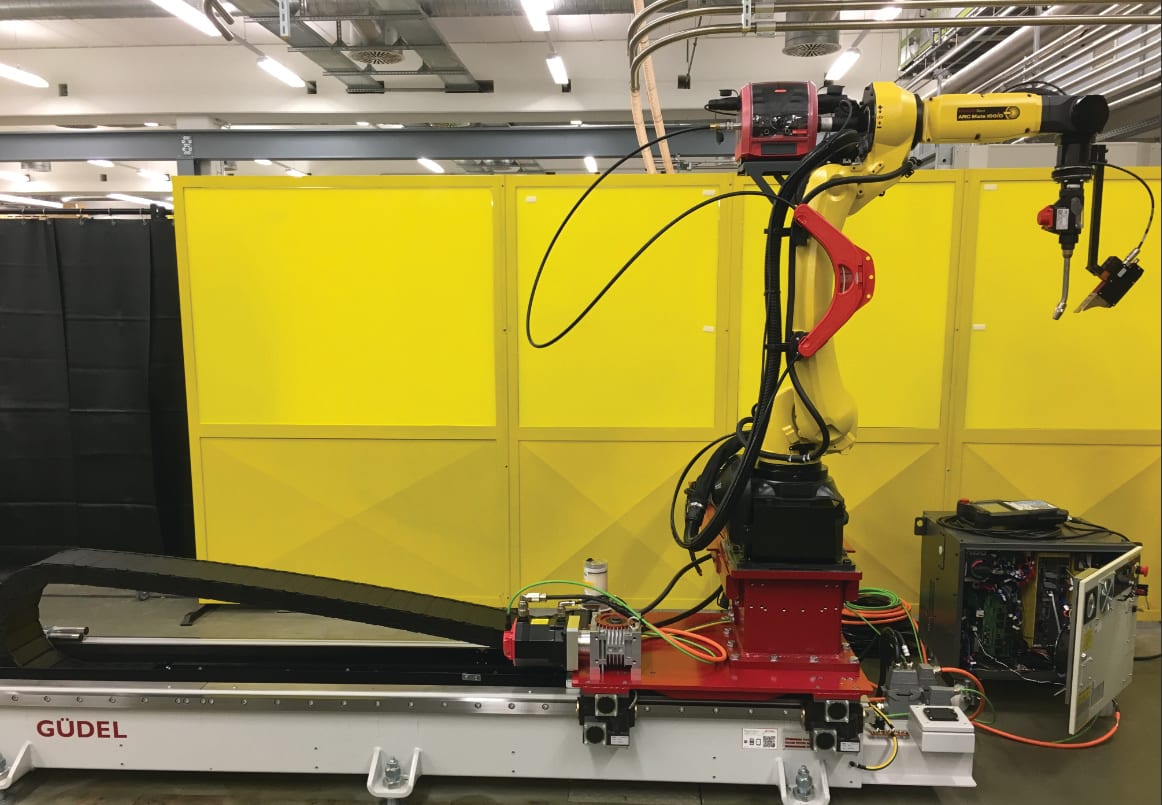
Figure 1: Not all ball bearings in linear tracks are able to withstand harsh environments. Cam followers from Güdel are examples of bearings that will keep robots running smoothly on linear tracks, even in applications with significant debris and small particle contaminants. (Credit: Güdel.)